
Parking Radar: From Schematics to PCB
A complete hardware build of a parking assistant, from schematics to a fabricated, routed 2-layer PCB and bench validation.
Supervisor: Prof. Ludovic Noury.
Built with: Mathis Dos Santos.
What it does
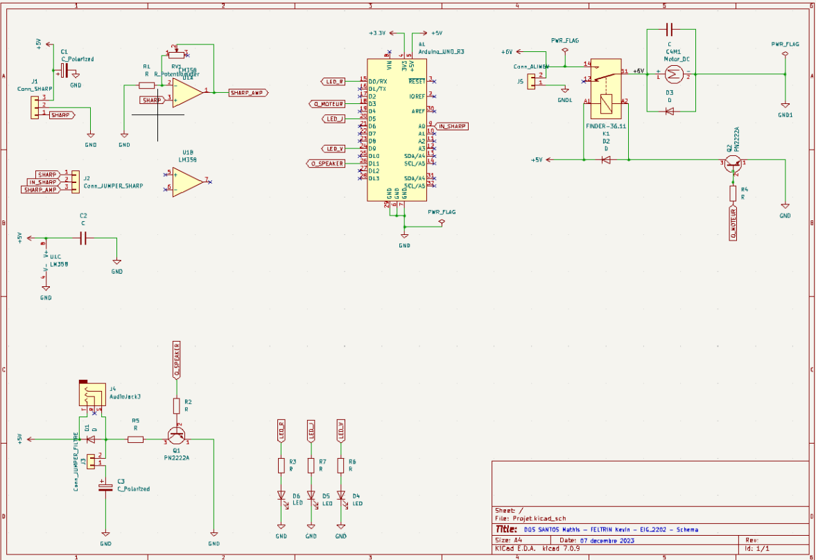
- Senses distance with a SHARP GP2Y0A21YK0F IR sensor (raw or amplified path).
- Drives a DC motor/actuator through a Finder 36.11 relay and PN2222A transistor.
- Speaker output with a selectable first-order RC low-pass filter for tone smoothing.
- LED bar indicates proximity on three channels.
- Microcontroller/FPGA-friendly I/O (3.3 V logic, 5 V power domain).
Design highlights
- Amplifier: LM358 non-inverting stage with adjustable gain (potentiometer), decoupled rails.
- Protection: flyback diodes on motor and relay, local decoupling (100 nF).
- Power: single 5 V supply; trace class sized for about 210 mA max on the 5 V net.
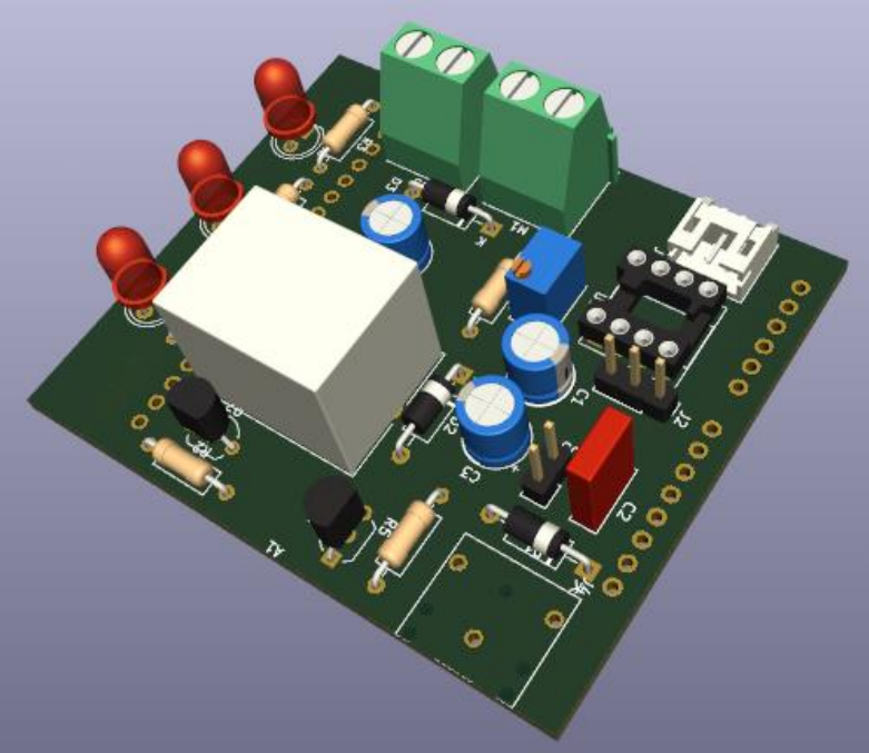
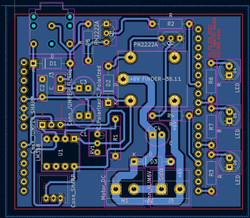
- Board: ~54 × 63 mm, 2 layers, 0 vias; labeled jumpers to select raw vs amplified sensor and filtered vs direct audio.

Notes
- Put the PDF report at
/files/rapport_pcb.pdf. - Save the images at:
/images/parking-radar-3d.png(3D render)/images/parking-radar-layout.png(layout)/images/parking-radar-schematic.png(schematic)/images/parking-radar-photo.png(real hardware photo)