CNRS / ESYCOM: Energy harvesting with TENG
Four-week research internship at the CNRS / ESYCOM Laboratory (UMR CNRS 9007).
Supervisor: Prof. Philippe Basset.
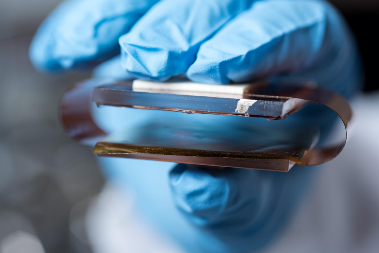
Goal: simulate and validate a conditioning circuit for a Triboelectric Nanogenerator (TENG) that harvests mechanical energy (vehicle pass) and powers a Bluetooth transmission to a smartphone.
Reference: Nature Communications: “Employing a MEMS plasma switch for conditioning high-voltage kinetic energy harvesters”.
Nature article Report (PDF, in french) Slides (PPTX)
Context & Objective
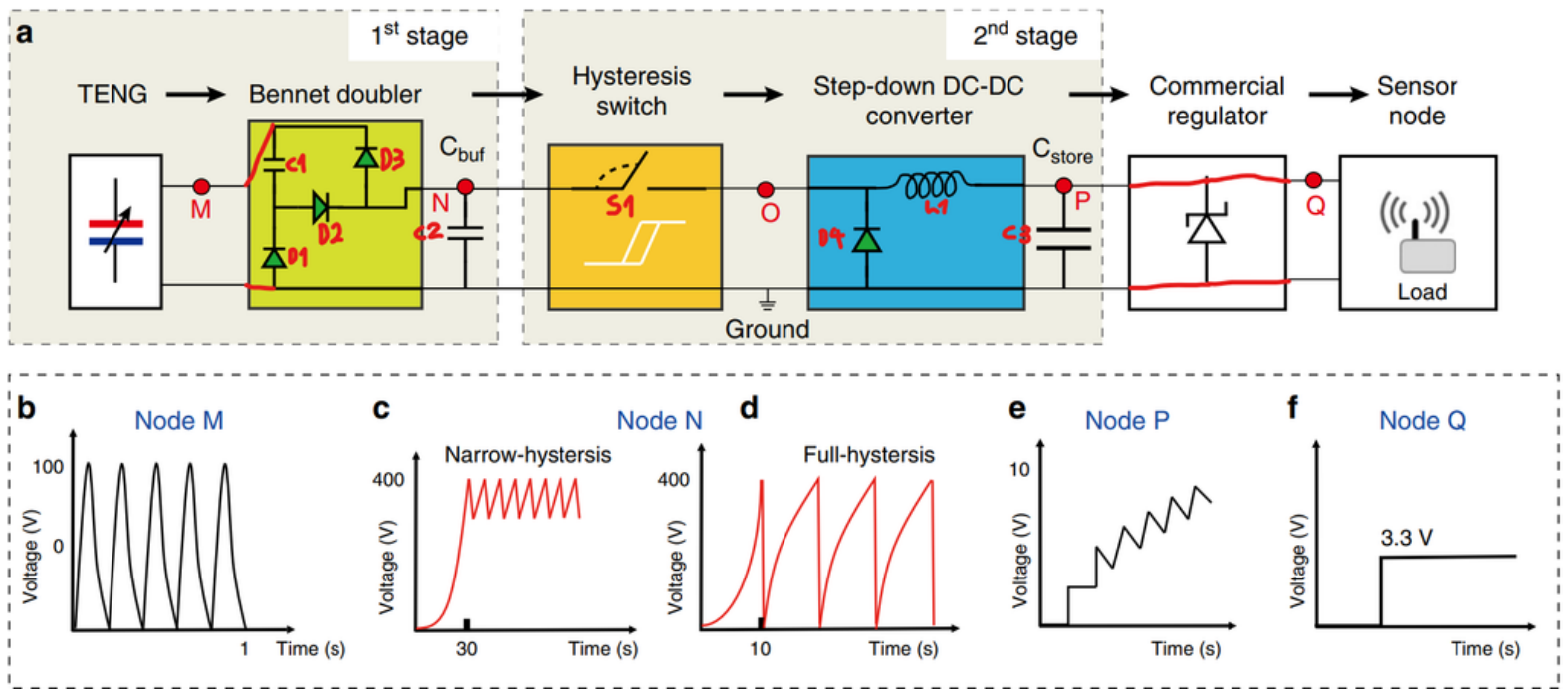
TENG devices deliver high-voltage, low-current, pulsed outputs, not directly usable by electronics. The project adapts the two-stage chain from the paper: Bennet doubler → hysteresis switch → step-down DC-DC → regulator to store energy and supply ~3.3–3.6 V for a Bluetooth node.
My task was to compare circuit options, model them in LTSpice, and verify behaviors on a bench prototype and on-site tests.
Approach
- Modeling. Full path in LTSpice with parametric sweeps of:
- Bennet doubler capacitors/diodes (charging efficiency)
- Hysteresis thresholds (switching stability & charge bursts)
- Storage & DC-DC (ripple vs. time-to-start)
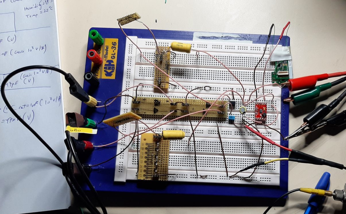
- Measurement. Prototype assembled; node voltages (M, N, P, Q) captured on scope.
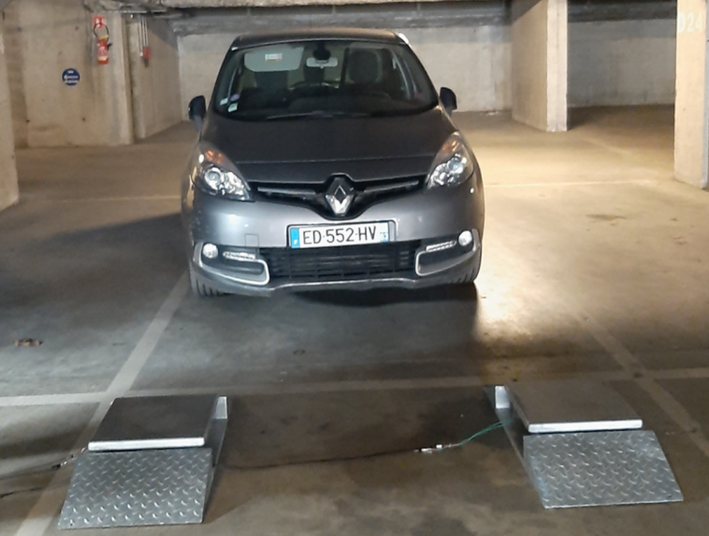
- Field test. Validation with a vehicle pass over the ramp; alignment/friction tuned for repeatability.
Selected results
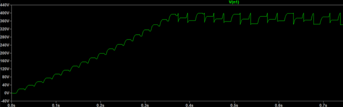
- Node N shows the expected sawtooth charge then burst discharge when the hysteresis triggers.
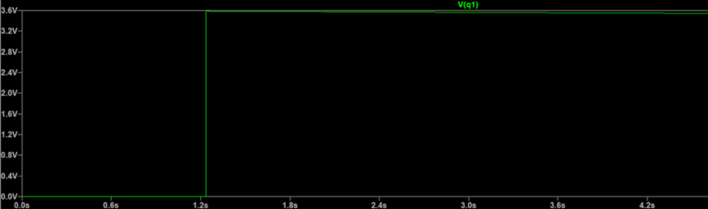
- Output Q reaches a stable ~3.3 V, enough to boot a Bluetooth node; storage sizing trades start-up time vs stability.
- Practical note: mechanical coupling dominates variance; small changes in ramp pressure/position noticeably affect available energy.
What I did
- LTSpice modeling & sweeps (Bennet, thresholds, storage).
- Bench measurements and consolidation into operating windows hitting the 3.3 V target.
- Recommendations: improved mechanical fixture, lower-drop diodes, and soft-start on the DC-DC stage.